Monday, March 30, 2009

Land of the Rising SUN, no SKY…line

I still remember the days when I found out about the Skyline through the original Gran Turismo and liked the fact that it was one of the faster Japanese Class A cars. However times have changed and instead of seeing it only in video games and on the silver screen, the Skyline GT-R has situated itself in the American market for a while now taking accolades from numerous stateside automotive journals. For instance, Motortrend named this nearly 4000 lbs beast it’s car of the year for 2009, which is pretty unusual seeing the past winners were cars like uh, I don’t know, Civics!? So what can we get from this other than the fact that those of us who are underprivileged enough to have not driven this thing is that the hype is real, more real than Obama for that matter (damn $3.55 trillion plan, sorry Democrat friends). Well, anyways, a few months ago at work we had the opportunity to do some minor work on one, so I decided to snag a few pics, make a few observations, and truly see if the engineering can back up the performance we’ve been reading about for the last year. So let’s have a go!

First off, the brakes (since I’m sure my first post is still fresh in your minds). This rotor is the biggest disc I have ever held besides the “il gigantis” at Ameci’s pizza. Well, for a big car, you need big brakes, and a six piston caliper mated to a 15” in diameter, two-piece rotor with an aluminum center is sure to stop this to its claimed 60 to 0mph in 108 feet which is staggering considering how much of a fat-ass this quick sumo wrestler is. The rear gets a little less love with a 4 piston-caliper and a thinner rotor, but it’s still 15” in diameter, because as we all know, size does matter.

What also is interesting is the fact that the caliper is a mono-block piece. What does that mean exactly? Well these brakes were probably initially casted into the general shape that you see above and were milled and drilled for critical dimensions and hole positions. This process retains the caliper’s structural integrity better when compared to a 2-piece cast design, however, more than likely requires more manufacturing time. What’s really unique about these specific calipers are the holes along the edge of each piston. Reason for these? Not sure but I’d assume it displaces heat due to conduction (the actual contact between two things e.g. non-existent conduction between women and myself) between the brake pad and caliper, and this of course will help in lower brake fluid temperatures.

Now if you guys look again towards the first picture (where the right side of the picture is the front of the car), you will notice that the upper suspension arm (A-arm) is angled towards the upper-right. This may seem meaningless to most, but this is Nissan’s engineering proof. With this angle, under suspension compression, the caster angle is going to increase which is great when traveling nearly 200mph and hitting minor bumps. Caster improves the straight-line stability of the car but it also assists in camber. Now the camber angle is on the plane which is perpendicular to the caster angle plane but parallel to the vertical axis (say what?). Just look at the picture below and it should all make sense.

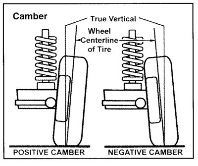
So the more caster angle added, the higher the negative camber angle gain will be when the suspension compresses. This helps this Japanese whale grip ever-so aggressively well even when things seem border line…impossible. As we all know, cars create a roll motion opposite of the direction of the turn. We may try hard to reduce the effects with stiffer springs and better damping, but in end it’s inevitable. In the situation of the GT-R, a little roll is a plus because as the negative camber angle increases, the roll will assist in allowing the contact patch of the tires to be fully employed. What does that mean? It means the car uses more rubber or rather more surface area of the tire which is in one word: good.

Another plus that the GT-R has is its trans-axle transmission. I’m sure you’ve guys heard the term tossed back and forth between magazines, forums, and other blogs but I’ll reduce it down to what I think should be the definition for it: transmission with side-mounted axles. The GT-R is able to retain an almost perfect weight bias by placing the transmission in the back. But wait a minute, isn’t it a 4WD? Yep, it sure is but Nissan drastically changed the drive train layout compared to the R34 to allow this GT-R to hang with the big boys straight off the showroom. See on older GT-Rs, the transmission was essentially similar to a front-engine, rear-wheel drive car like an S2000. You have your longitudinal engine (series of cylinders runs parallel to the side of the car) and right behind it was your transmission and out of the transmission came a driveshaft. The older GT-Rs had a very similar layout, but with a transfer case. What’s critical to note is this transfer case took all the torque traveling parallel with the side of the car and switched it perpendicularly so that the torque would be parallel with the bumpers. Essentially a transfer case “transferred” torque from the driveshaft’s rotations to the front axles. This is problematic. Transfer cases are largely confined because they typically have a lot of things going on next to them: exhaust pipes, the transmission, steering racks, and the driver/passenger’s ass depending on what side of the road you drive on. This of course adds limitations in size which highly affects the strength of the transfer case. Nissan thus saw the several benefits of running a rear mounted transmission because it allows them to create a beefy transfer case in the front of the car. However, this results in two drive shafts: one from the engine to the transmission and another from the transmission to the transfer case. For me, I saw this as a plus, even with the extra driveshaft. With this setup and remembering that all materials have molecular play, the rear tires will have the initial bite when the throttle is applied, allowing for higher torque bias to the rear when disregarding the electronic systems that the car has.

Lastly, I want to discuss the front lower control arm design. Notice the bend that it has for clearance between itself and the tie rod (the steering arm; black rod with the ribbed rubber boot). Most of you may be thinking big deal, the steering rack had to be offset low due to the big V6 motor. To me this is not the case. An issue that several cars and many “tuner” vehicles face is bump-steer. Bump-steer in short is the irregularities of arc movements between suspension arms and the steering arm which causes the wheels to slightly turn when the suspension compresses. Imagine it more like this: bump-steer is like a messed up rainbow where the red arch clearly crosses over all the way into the purple arch and the rainbow is so messed up that it looks like the first picture you drew with a box of crayons. See the colors represent the arc motions of the suspension components. A harmonious and bump-steer-less system needs to be like a rainbow (I know that sounds gay). If the steering arm’s arc of motion were the red arch, it needs to be the bottom arch all the time and in the same way, if the purple arch where the control arm’s arc of motion, it needs to remain as the highest arch. And getting back to the point, Nissan purposely placed that bend in the lower control arm to make sure that the system was bump-steer-less, like a big, gay rainbow.

Well I’m literally out of gas and energy now guys. I’m sorry for the shitty metaphor but that was all I could come up with. Thanks for reading

-Josh

Thursday, March 26, 2009

RADIO TRANSMISSION...actually just transmission

Hey everyone,


Well after yesterday's blog, I decided to dive deeper into the GT3 RS at work. When all the modifications are complete, this thing will be (in all honesty) a track monster. The GT3 is an already capable car at any course and the GT3 RS is even more "balls to the wall." However, this costumer is taking it to the extreme (say it like the bro-punks from "Harold & Kumar") with new coil-overs, a sequential shifter adapter, solid spherical control arm bushings (which replaces shitty factory rubber filled ones), "dry" carbon hood & fenders (the real carbon fiber, not your Import Tuner style fiberglass wet-lay), lexan rear quarter panels and rear windshield, an aluminum flywheel, a multi-plate clutch (which is comparably smaller in diameter than the stock friction plates) and a new final drive. So the owner is pretty much taking a bad ass super car and making it more bad ass by reducing weight and rotational mass while improving the cornering capabilities of the car.


Our main topic today is the transmission. As stated before the final drive was changed for a larger ratio (3.9 to 4.1 I believe) which does reduce the top speed, but in all fairness for quicker acceleration off the line and out of the corner. So lets take a look.


At first glance, anyone can notice the use of fins all along the transmission. They act as gussets reducing the effect of torsional loads (especially from drivers who think they can drive, but in reality, can't) and strengthen up the transmission. This allows for the a smaller amount of aluminum to be use (as in our case, this whole thing is made up of cast-aluminum, but not the gears...dummy). These fins also dissipate heat which allows for a more constant oil viscosity reducing the heat and wear experienced by the gears. To me, this transmission looks beautiful like a piece of art, but unlike the indie art shows I've gone to, this art has a function and purpose.

The major thing that separates this from any other Porsche transmission or 99% of other manual transmissions out there is the built in oil cooler. As you can see in the picture above and in the 2nd picture from the top (where it sits right of the transmission), an aluminum box cools down the gear oil that runs through it. In the transmission sits a small mechanical pump (no electronics here) that runs off another gear and shaft in the transmission. It then runs through this small heat exchanger dissipating heat into the atomosphere. But wait, why are there entries and exits on the aluminum heat exchanger? Porsche, knowing full well that the ambient air will cool down this transmission's temperature (which is in excess of 200 Celsius), knew that coolant would act as a better heat absorper than air. Let's think about this for a second. Your coventional rotating heat lamp will keep your lonely-ass slightly warm in a cold room only when it points at you, however, a hot bath will keep you warm for hours, even when the skin-scathing water is turned off. Water (which is largely what coolant is) absorbs heat well and with a kick-ass cooling system like the one on the GT3 RS with its multiplte radiators and aluminum pipes, dissipates heat extremely well. So these entry ports (right of my hand, covered by a blue towel in the picture above) allows coolant to travel through this aluminum box, cooling down gear oil temps. Genius! What's more to say is that the system is simple, effective, and doesn't rely on the use of electronics (oil temp sensors, electric pumps, etc.) which, come on lets face it, will break sooner than its mechanical counterpart or will become hazardous when the system no longer has power.

Well after getting excited about a transmission out of a nearly $200,000 car with almost $100,000 invested into it, it's time I face reality which has come through a leaky refridgerator and a $375 asking price to fix it.

Cheers,

-Josh


Wednesday, March 25, 2009

Where to begin!

Readers,

First off, I would like to introduce myself. I am a car enthusiast, no wait, an aficionado. I find the engineering, passion (and sometimes, the manufacturing) amazing. Some base their liking of automobiles by the lines and the artistic concepts expressed through vehicles. I on the other try to look deeper, at individual components and the basis for why things are the way they are. However, the true reason for this blog is to keep myself asking why and to assist (well, to try) my mind from becoming a non-progressive, stagnant human organ of post-graduation laziness. I will give my earnest attempt to post 3-4 blogs a week which may be more than I'm asking for. But it really depends on what I see at work, so the more kickass stuff I see, the more I will blog. So, lets dive into things!

My first topic that I would like to discuss are ceramic brakes. Nowadays, ceramic pads and rotors are commonplace with super car manufactures and more recently, with Nissan under the debut of the GT-R Spec-V (which we don't have in the states yet). Ceramics (from what I remember as a student) is the abnormally high concentration of carbon mixed into materials. So how can a commonplace steel rotor be improved by a ceramic rotor. Well for one, lets imagine that a steel rotor is like a sponge cake. Our sponge cake has tons of air pockets most likely full of oxygen and nitrogen (the stuff in the air). Now, instead of a sponge cake lets say our batter of a carbon and steel mixture was used to create a pound cake. The pound cake is packed with less air pockets, however, since our pound cake is a mix of two things, those old air pockets are now full of carbon.

You see, carbon is one of the hardest and smallest particles on the face of the planet. Carbon makes up diamonds, diamonds! There's a reason why "diamonds are forever" and that you can cut or vandilize just about anything with a diamond. But you may be asking, "wait a minute, carbon makes up coal, and coal just falls to pieces when I burn or throw it." But did you know that artificial diamonds can and are made by highly compressing large amounts of coal into small "fake" diamonds? And the mixture of carbon into steel gives us the ceramic rotor.

So, in reference to the cake metaphor, the ceramic rotor is stronger. But what about weight? Due to carbon's strength, less iron can be used to manufacture a rotor and that saves weight. This produces a rotor that is lighter and stronger. And since these air pockets (which are sensitive to heat and cause expansion when pedal pressure is applied) are full of carbon, there is less air and a smaller amount of expansion under hard braking. Last but not least, this reduces rotating mass which aids in later braking and quicker acceleration.

However, due to the reduction of friction (which is common with ceramics as ceramics have even been used over steel in ball bearings), the rotors are pretty shitty in the cold. The pads and rotors thus have to be "warmed-up" before aggressive driving and have a key operating temperature for optimum performance. With the reduction of friction though is the increase in longevity (which is also aided by the added strength) and the technician at work tells me Porsche ceramic rotors will probably last longer than the cars themselves!

But is not worth it in the end? Of course! A rotor that is significantly lighter than its steel counterpart while improving off-the-line and out-of-the-corner performance and improved braking is a wanted must for any enthusiast. However, the price of true ceramic rotors and pads come at a cost. Supposedly, the cost of the ceramic rotors and pads on the GT-R Spec-V are a bit under $50,000 for all four corners, but then again we are talking about a 15 inch rotor. On that expensive note, lets look at some real-life ceramic rotors, the ones below are off a coveted 997 GT3 RS at work.


First thing you should notice is the "two-piece" design. The center on this particular rotor is a cast aluminum piece. The use of aluminum allows for a light-weight rotor and great heat dissipation. However, Porsche engineers have taken it to the next level to make sure that the heat created under braking does not interact with drive-line components (wheel bearings, C.V. joints, etc.).

As you can see, the rotor and the aluminum "hat" (center) do not actually touch. Thus, the only thermal exchange can only occur through the pins (shiny, fat "H" shaped things) that hold the rotor to the hat which again reduces the amount of heat exposed to drive-line components. One of the coolest things about this particular rotor is the female threaded pin. It has a small slit through the center of it, allowing for a slight compression when the bolt that threads to it is properly torqued down. Porsche engineers, in all honesty, never cease to amaze me.

On the back face, Porsche engineers have decided to use a TORX style bolt. The only valid reasons that I can think of for using a TORX style bolt is to reduce over torquing and to avoid clearance issues (and possibly because its a German thing). Another cool thing is if you ever had to change the rotor, you simply unfasten these TORX bolts from the drive pins allowing you to reuse the aluminum hats.


These things compared to the two-piece brake rotors we have at work are WAY lighter. I usually struggle carrying around a 350mm steel rotor with an aluminum hat attached but this piece is at least half the weight of that, and larger in diameter! Well, I've written for over an hour now, so I think its time to take a break. Thanks for reading!

-Josh